
Yup, ChatGPT made this image with direction
An ELI5 Explanation of Electricity and the Power Grid
The electrical grid is an amazing system wherein power is used almost exactly when it is generated. I love learning more about it, and I am blessed to work with and lead some amazing teams in the electrical grid planning space. It has taken me a fair bit of effort, a few electrical engineering classes I was fortunate enough to meet the prerequisites for*, much bugging of some of my favorite electrical engineers, getting things wrong and being corrected, and a lot of YouTube (shoutout to Practical Engineering) to feel like I actually understood the fundamentals of the electrical grid. And there is loads I still don’t know. So, my objective in this article is to explain the fundamental pieces at a level more people can understand!
So, what is electricity?
Electrons moving through a conductor creates an electrical current that results in electricity. But electrons don’t really flow in the way most people imagine. The wires already contain electrons, so it’s more like marbles in a tube: when you push a new marble in the negative side (voltage), an electron is pushed out the other end, the positive end, thus creating a current. This results in electricity created virtually instantaneously.

Where does power come from?
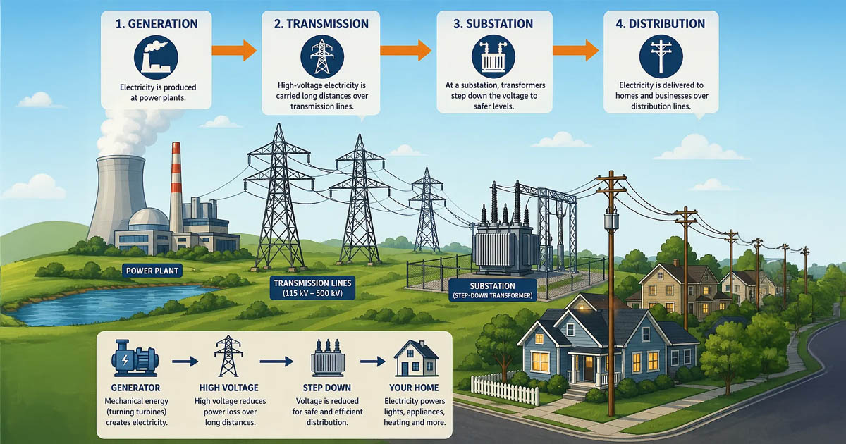
There are three core parts to the electrical grid: generation, transmission, and distribution. These core pieces also define the main business
structure within the electric power industry and markets.
Generation
Electric generation converts mechanical energy into electrical energy using generators driven by turbines powered by steam, water, wind, gas, or diesel engines. Common generator types include synchronous generators, induction generators, and permanent-magnet generators. A step-up transformer is often required to facilitate the transition from generation to transmission to bring the voltage to the correct (high) value.
By raising the voltage, step-up transformers allow power to travel long distances more efficiently and with lower energy losses. Sending the same power at a lower voltage would require higher current, thicker conductors,
and much more expensive infrastructure to build and maintain. Beyond the technical problem, power grids are always trying to keep the construction and operational costs as low as possible.
Transmission
Transmission systems are a great big synchronized machine. AC transmission grids are a network of generators locked together by electromagnetic coupling, wherein any new generator must match various characteristics of the whole system:
- frequency
- voltage magnitude
- phase angle
- phase sequence
- grid inertia
And if new generators don’t match these characteristics, the equipment trying to connect is damaged. Fortunately, autosynchroscopes make this connection and disconnection process easier, and many generators have mechanisms that allow repairs to be made while the equipment is still “on”. As a result, everything in an interconnection operates at the same frequency. To me, this is mind-bogglingly beautiful: imagining generators at the Callaway Plant having the same frequency, which is standardized to 60 Hz (cycles per minute), as the Wateree Hydro Station. 60 Hz is the standard in the US, but other countries might have different standards. 50 Hz, for example, is a common standard in large parts of Europe, Asia, and South America. Because power systems in different countries may operate at different nominal frequencies, cross-border energy exchange often relies on HVDC links for conversion.
The grid has a natural tendency to resist sudden changes in frequency and other metrics, a la grid inertia. This concept is fundamental because it helps explain the mechanical behavior that enables large generators to synchronize with the grid. It also explains why power engineers are concerned with connecting inverter-based energy resources, which do not naturally provide inertia and therefore complicate interconnection. As more inverter-based resources like solar PV and battery systems connect to the grid, system inertia can decrease because they do not naturally provide large rotating mass like traditional synchronous generators. To address this, many inverter-based resources now use controls that simulate inertia during grid connection.

These transmission systems are a meshed network with many interconnected paths, which promotes redundancy and therefore reliability and stability. N-1 Security is built into the system, largely organically, which means that a line, a transformer, or a generator can be lost without power failure. This allows power markets to function so that, for example, wind in Missouri can serve New York City.
Transmission systems have high reactance compared to resistance because at high voltage, conductors are large, which yields low resistance.
X/R = reactance/resistance
Lines are long and widely spaced, which results in higher inductance but generally low line losses; inductance is a property of conductors where they tend to oppose changes in electrical current by storing energy in a magnetic field.

Capacitive reactance is another important consideration in transmission systems, which is the reason lines are typically so high above the ground; here, there is an electrical field between the earth and the ground. This can result in overvoltage during periods of low load demand. In general, capacitors are temporary batteries that charge and discharge rapidly.

Transmission systems are also typically assumed to be balanced three-phase (A, B, and C), even though they reach those peak values at different times.
Distribution
While transmission systems form a meshed network, distribution systems, which start at the substation between high-voltage transmission systems and lower-voltage distribution systems, are either radial or looped.

As hinted at in the above image, radial systems are a bit less reliable because if there is an outage, everyone downstream is impacted. These types of systems are typically found in rural or older neighborhoods. Depending on where the fault occurs, it could impact the whole neighborhood or perhaps just those with the same service drop, which could possibly be only a few service points.

The voltage in the distribution system is significantly reduced from the voltage of a transmission system. While transmission systems may see voltages up to about 765 kV, they’re usually about 230 kV at the substation, and about 240 V at an individual service point. This reduction happens through a series of step-down transformers.
Whereas transmission systems have high X/R ratios, distribution systems have low X/R ratios. Lines are thinner and less conductive, the lines are shorter and closer together, and they operate at a lower voltage. All this results in a reduction in reactance, which makes resistance more prominent.
Does all the power generated get used up?
Well, not exactly. There are different sources of loss along the way.
Generation Losses
Different generation technologies have different dominant losses, though some of the losses found in transmission systems also apply here. So, losses are not as streamlined as they are in transmission and distribution parts. Generation losses could be:
- Steam plant losses → Steam plants lose large amounts of energy as waste heat because thermal energy cannot be perfectly converted into mechanical and electrical energy due to limits described by the Second Law of Thermodynamics. Heat is commonly lost through cooling towers, condensers, exhaust gases, and auxiliary equipment like pumps and fans.
- Wind turbine losses → Wind turbines experience aerodynamic losses because blades cannot capture all of the wind’s energy. Turbulence, wake effects, blade-tip vortices, and imperfect blade angles reduce efficiency. Additional losses occur from friction and vibration in gearboxes, bearings, and generators.
- Solar PV losses → Solar panels lose energy when sunlight becomes heat instead of electricity. Reflection losses, inverter losses, wiring resistance, and semiconductor inefficiencies all reduce output. High temperatures further decrease panel efficiency by lowering voltage production.
- Hydroelectric losses → Hydroelectric systems are highly efficient because they directly convert moving water into rotational energy with few conversion steps. Losses mainly come from turbulence, friction in turbines and penstocks, cavitation, and electrical losses in generators and transformers.

Transmission Losses
Transmission systems
- Copper losses → These are also called I²R losses, where I is current, and R is resistance. Colloquially, they are called “copper losses”, though all wire materials may experience this power lost to heat, and this type of loss is most common in high-voltage/low-current systems. If the lines are hotter due to high ambient temperature, that can result in somewhat increased copper losses.
- Corona losses → Power will dissipate when an electromagnetic field ionizes around air molecules. This can result in a whirring noise you hear around transmission lines. It can also sometimes cause radio interference. Weather can have a big impact on corona losses; sandstorms, rain, fog, snow, and really any increase in moisture around the lines, as well as ionization in the air, can all impact the amount of corona loss.
- Dielectric losses → Energy can be dissipated in any insulating materials used on the transmission lines.
- Charging losses → Losses due to capacitive reactance (mentioned above) can result in some energy lost to the earth itself.
Distribution Losses
Distribution system losses generally fall into one of two categories:
- Technical losses → These are natural energy losses that occur as electricity moves through the physical power system. Examples include copper (I²R) losses in wires, transformer losses, reactive power effects, and small amounts of heat dissipated by equipment. Utilities reduce technical losses through better conductor sizing, higher voltages, efficient transformers, capacitor banks, automation, and grid modernization.
- Non-technical losses → These are losses not caused by physics, but by operational or human factors. Examples include inaccurate metering, billing errors, and electricity theft. Utilities reduce non-technical losses using smart meters, analytics, inspections, and improved operational processes.

Conclusion
I hope this article helped you learn about the pieces of the electrical grid (generation, transmission, and distribution) and how they fit together in an approachable way! At New Math Data, we have many customers in the electric utility and power space, and it is not only immensely topical for the future of humanity but deeply interesting. Please reach out or comment below if you have any related ideas you would like to discuss with us!